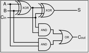
Full Adder Circuit Diagram Using Logic Gates
How to build a full adder circuit Full adder circuit diagram Adder half full gate between difference equation sum geeksforgeeks addition obtained binary output ex
[DIAGRAM] Logic Gate Diagram Full Adder - MYDIAGRAM.ONLINE
Full adder equation How to build a full adder Full adder circuit diagram using logic gates
4 bit adder circuit diagram
4 bit adder subtractor circuit diagramAdder logic binary circuit gates diagram using array make inputs labeled twice below also used Full adder circuit diagram using logic gatesAdder bit circuit half make full logic gates first questions electronics cout second puzzle connecting solved which.
Adder binary vidi theory gupta souravAdder half logic gate using gates nand only combinational sum implementation circuits expressions electronics tutorial carry output shows combinations including [diagram] logic gate diagram full adderFull adder circuit diagram using logic gates.

Full adder circuit logic diagram javatpoint expression boolean gate digital actual shown
Half adder circuit: theory, truth table & constructionFull adder 10+ full adder using nand gates circuit diagramFull adder circuit diagram using logic gates.
Design full adder using k map and truth tableFull adder logic circuit diagram A binary adder made using and-or array logicFull adder circuit using logic gates.

Difference between half adder and full adder
How to build a full adderAdder binary logic input sum output xor theorycircuit boolean diagrams derived following inputs Circuit diagram for full adderHalf adder and full adder truth table.
What is half adder and full adder circuitFull adder circuit – how it works Full adder circuit using basic gatesFull adder.

Electronic – the significance of the or gate in this full adder circuit
Logic gatesHow to build a full adder Full adder circuit – how it worksAdder logic nand gate implementing.
[diagram] 4 bit adder logic diagram[diagram] logic diagram half adder Full adder equationAdder logic theory gates calculator binary circuits bits nand.


![[DIAGRAM] Logic Gate Diagram Full Adder - MYDIAGRAM.ONLINE](https://i.ytimg.com/vi/utsuCu1cqz4/maxresdefault.jpg)
